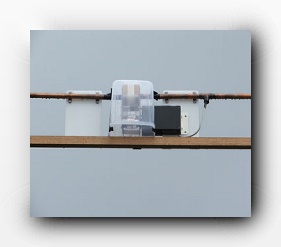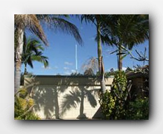
The aerial is up. The rotator worked first time with no overrun at all. Shaft locking solenoid with micro switch interlocks have been fitted.
The Q is higher and the impedance changed as the SWR went up to 2.5:1. A quick adjustment of the gamma match and I had it back to 1:1.
Another 9 + 15dB carrier on 3.61mhz was reduced into the noise by a 15 deg rotation of the loop. Still getting great signal reports.
I have just tested the loop on 40m and 160m. To get the loop on to 160m I had to place a 560pf 35KV door-knob cap across the 100pf vacuum variable. The problem with these caps (and most caps) apart from ther low Q, is the change in capacitance with heat. On a sunny day a cloud going over will change the capacitance enough to shift the SWR from 1:1 to over 5:1, so you can imagine what a bit of RF heating will do.
I was able to transmit for a short time with 20 watts. I made two good contacts about 120km away on the other side of the mountain range. This is with very low efficiency caused by the doorknob capacitors low Q killing the loop efficiency when placed across the vacuum capacitor.
2s points. Once again it shows how important the capacitor is
to loop preformance. With the Q and efficiency losses caused
by the low Q doorknob fixed capacitor even the receive signal
is down when compared to a vacuum capacitor.
The noise floor on the vertical on 160m is S8 on a good night, S9 on most nights and +20 to +30 dB on
bad nights. The noise floor on the loop is S2 to S3 (S4-S5 with only the vacuum capacitor - see below)
At first I thought the loop was a bit deaf until a station that I have tried to copy for over a year came up at 20dB over S9. This was at 3.30 in the afternoon. The receive signals at night were wall to wall with a background noise level still at S2 to S3. I have started saving for a higher capacity vacuum capacitor to cover from 160m to 40m.
UPDATE:
When the new 1000pf vacuum capacitor was fitted, the noise floor and signals increased about 12db or
The results on 40m have been fantastic. I have worked overseas stations and even in a few dog piles
I have been answered on my first call.
Stations interstate have said that they thought that I was using a big dipole - This loop preforms.
The signal just stays so solid. I am able to null out local interference on 40m to the same degree as I have on 80m.
I know this loop may not work as well as a full size dipole at height, but I can not put up a dipole, let alone one at the correct height. This loop will beat a small vertical and a dipole at less then a 1/4
wave high most times because of the radiation angle and ground loss of the low dipole. A short vertical will suffer huge ground and feed losses
with poor earth and loading. The noise on receive that a vertical has in this noisy suburban environment makes hearing most signals very hard.
The ability to null local interference with the loop is a God send. If I can’t hear it, I can’t work it.
I wrote the following after finding out how great 80m worked - I still had no idea at this stage just how great 160m would also turn out to be.
A lot of Hams look down on the loop antenna. They will try and compare a loop or a small antenna to a dipole. This is meaningless if you can not put up a dipole in the first place! This is not a small 1 meter loop which so many try to load up on 80m inside the shack and then compare it against a big aerial. This is not a poorly built wire or copper loop.
There is no room for cutting corners when building a transmitting loop. A poorly constructed and sited loop will not work correctly.
This loop is 3.6m in diameter and it really does work as well as the ARRL Antenna book says. It works on both DX and local contacts and has quite good radiation angles. Compared to the short vertical it is up to 30db stronger on transmit and receive to loacl signals and is always at the very least 6db stronger on transmit and receive to DX signals -Yes I know my short vertical was inefficient, but it's the best I could do with the limitations imposed by this site.
Some interesting points about this loop so far:
The Gamma match is fine on 80m and 40m, however it has to be adjusted on 160m to get the SWR down. I tried a remote adjuster for the gamma match and it works a treat.
-NOTE-
I have since found that the Gamma match change is caused by the Q of the fixed capacitor used when testing 160m. It seems that using a cap with a Q lower than a vacuum cap causes a resistive loss in the loop, so I think that the loop impendence changes and so the position of the gamma match must be adjusted to match this change.
I made a high Q cap from PCB and Teflon and in a low power test I was able to get a 1:1 match on 160m with the gamma match in the same position as 40m and 80m.
-UPDATE-
I have fitted the new 1000pf vacuum capacator and the SWR is now 1.12:1 on 160m, 1.26:1 on 80m and 1.12:1 on 40m. (Vector Analyst)
The signal to noise ratio on 80m is exactly the same as my small 1 meter electrostatic shielded loop. The deep nulls of the small balanced loop are repeated in this big copper loop. I had not expected it to null so sharply and so deeply.
There is a TV aerial 2 meters away from the loop, just below the bottom of the loop. There is no interference on the weak TV reception from this aerial. The main aerial in the house fires straight through the loop, there is no interference on digital or analog TV reception and it has a mast head and distribution amplifier.
Just 0.1pf will shift the loop resonance enough to change the SWR from 1:1 To 5:1 This just highlights how important the tuning cap is and how important it is to have very fine resolution in the motor drive to the cap. Wind and rain have no effect on the loop tuning. Birds will detune the loop, a quick pulse with 100 watts will remove the bird!
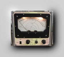
Select Tune on the combined unit. The power from the rig is dumped into the dummy load. A small RF sample (a few milliwatts) is taken to the
50 ohm RF resistance bridge with the loop switched in as one leg of the bridge. The Cross needle meter shows forward power into the load but
the Reflected part of the meter shows the bridge balance. Rotate the loop tuning for zero balance and you have a 50 ohm match.
Switch back to Aerial and you are on the air.
The only downside is having to adjust the SWR when ever you change transmit frequency. I feel the advantages in a noisy environment and limited space far outweigh that. However the advantage of that narrow bandwidth and hi Q, really showed up in the contest with very close strong signals.
If you have no need to null out LOCAL noise then you don’t have to make the loop rotatable. Rotating the loop has little or no effect on signals coming in above 30 deg, and has almost no effect on stations over 30 to 100 kilometres away. However it has very sharp nulls to local noise and carriers, removing even 20 over 9 interference.
Combined Homebrew Unit
RF bridge
Directional Coupler
Dummy Load (1kw ssb)
Includes Peak reading
OP amps
RF bridge
Directional Coupler
Dummy Load (1kw ssb)
Includes Peak reading
OP amps
On Air - HF Copper Loop for 40, 80 and 160m
I can honestly say that this aerial is FAR easier to tune than an ATU and a long wire.
The peak on receive is so sharp that the SWR on TX is almost 1:1 after tuning for maximum receive noise.
With one knob tuning and a home brew COMBINED “RF-sampling impedance Bridge - Dummy load and Cross needle Directional Coupler” I can tune up anywhere on the band without putting a carrier to air in less than 3 seconds.
Click Image to
enlarge


