


The Start - HF Copper Loop for 40, 80 and 160m
I found two sites that had at least given the loop a chance to work; their results were encouraging. I proceeded to design my own loop and find
a way to rotate it, make it freestanding and allow it to be tilted over for servicing the tuning unit and to protect the loop from cyclones and 100k
or more winds that we sometimes experience here in Queensland. Not an easy task! What follows are the results of my efforts.
Be sure to read Leigh's - VK5KLT - paper titled the Underestimated Magnetic Loop Antenna - Helps bring things into perspective.
Overview - Looking back.
I have used this loop for over six months on nets with around ten or more stations. I have three to four stations within 15km of me and another four within 100km. The result that almost blinds you with its never changing consistency under all band conditions - especially when propagation is poor - is this loops transmit performance on 160m; Especially over long distances. This loop really competes with full size dipoles on 40m and consistently outperforms then on 80m and 160m. A lot of these dipoles are well built with open wire feed and a few mounted over a ground plane to help minimise the loss of low height induced currents. How many of us can get a full size dipole up over 120ft in the air on the 160m band?
Don't think you need to? Then don't be surprised if one of these small correctly built and sited loop antennas competes with or outperforms you.
I am often the strongest signal over distance and sometimes the only signal heard interstate in bad conditions on the net. This aerial remindes me of the 160m ¼ wave vertical with full ground plane that I has on acreage. Stations then, as now, receive my signal loud and clear even thought their transmit signal hardly gets back to me. Yes! I can hear stations as loud as any dipole near me and usually receive long distance stations stronger then the dipoles. What I am now highlighting is the difference in efficiency between their aerials receive capability and it's transmit loss.
Short verticals are no match on 160m, except for the one mounted over salt water about 15km from me, and then only on transmit to interstate stations (he and I were the two strongest signals) but it was no match on receive under any condition. This is every week, month after month and in our summer with some of the worst noise and propagation conditions that we have experienced for some time. My location is low with poor ground and +20dB local noise -I have tried numerous aerials at this location over the past two years - This loop has unbelievable performance.
"I know it beats me, I can hear the reports, but I still don't have to believe it" a local ham friend (at least he was) with a full size 160m dipole at 45ft over salt marsh near the ocean commenting on the signal reports from the north to the south of Australia and over to New Zealand after a few of the 160m nets. I don't think that I can convey in words my disbelief as I logged my first signal reports on the 160m net with this antenna.
This loop is 3.6m high and 1/13 of a wavelength long on 160m! I read the net information about loop builders experiences. I then visited most of the big antenna internet sites that had modelled small loops. They told me they could not possibly work in a fashion that would allow them to be a serious aerial. They advised that other compact aerials - even mobile aerials - were a better choice if space stopped me from putting up a "bit of wire" in the sky. They had me convinced that loops were very poor transmit aerials and that 80m might be possible but 160m would only be of use for listening or at most, a few local contacts. Recently Leigh VK5KLT sent me an e-mail with the following quote. I think it fits in about here.
As Mark Twain once said, "It ain't what a man don't know that gets him in to trouble; it's what he does know for sure that just ain't so!".
The question remains - Why do so many of the home-brew loops fail to operate efficiently, even on their highest operating frequency? Why do most operate like leaky dummy loads on their lowest frequency? I hope this site goes some way towards answering these questions.
Starting out.
I was determined to give this loop every chance of working. It is constructed from 3/4" hard drawn copper and every joint is braised. I then
welded 6" x 4" copper plates to the top ends of the loop for mounting the tuning vacuum capacitor. There are no connecting leads of braid or coax outer strap. These are big loss items when carrying high RF currents. I see so many people building copper loops, attaching the tuning cap with flying leads and then proclaiming that the loop theory must be wrong or that loop antennas are inefficient and don't work. I wonder why?
I had an old 5-100pf 15kv vacuum capacitor of unknown condition in my junk box, I decided to try it and placed a 100pf 35kv doorknob capacitor across it to get the loop to resonate on 80 meters for a test. Note: This transmitting doorknob capacitor will kill the efficiency of the loop. Most caps - except air and vacuum - have a low Q. The correct variable cap to cover 160m to 40m is around 15pf to 700pf. This loop required 27pf on 40m, 170pf on 80m and 650pf on 160m to resonate. There are current and heating considerations that have to be allowed for with a vacuum cap - especially when partly meshed. Fortunately with low duty cycle SSB and our power limits we are usually within spec under these conditions.
I tried the loop on the ground before going to the trouble of making a rotator and mounting the aerial
on the roof of my shack. There are two 6m sheds 3m away and a fence of iron 3m away on the 3rd
side. I expected the near field induction and the almost complete shielding on 3 sides to make the loop
act like a dummy load. Remember, this aerial is only 3.6m high, just 1m higher than the sheds.
Now I know that a 40 ft vertical is not a good aerial on 80m but it is all I can erect on this site and the loop simply leaves the vertical for dead, by as much as 30db on local RX and TX due to the skip zone, and at least 6db on long distance. Radiation angle, polarization and efficiency all come into play in various ways.
Most hams run low dipoles which are good NVIS radiators and will work VK and ZL and some DX with what's left of the lower angle radiation. A vertical antenna has problems receiving high angle local contacts, this explains why the loop is better here, but the loop beats my small vertical on interstate and DX as well. So the loop, as the theory states, does appear to have both low and high angles of radiation. Every vertical variation and small dipole variation I tried faded in comparison to this loop.
It highlights just how inefficient a short vertical really can be, even when I tried a capacitor hat or converted it to an inverted L. It also shows
how much loss a dipole can have when mounted a fraction of a wavelength above ground which is often the case on 160m. The loop was very
impressive when it came to removing local power line noise and a 10 over 9 local carrier (interference) was completely eliminated.
I incorporated a 1.8 deg stepper motor and a rotary encoder to turn and track the position of the 20 turn vacuum capacitor. This is connected to a control unit that I designed and wrote the Micro controller code for. It drives the stepper and displays the position on an LCD. Another rotary encoder is used to adjust the vacuum cap, also included are fast CW/CCW push buttons. Stop to stop (20 turns) in 7 seconds. One revolution of the encoder turns the cap about 1/10 of a turn. It is a dream to tune, however with a bigger vacuum capacitor I will have to use a 6 or 10 to 1 reduction drive between the stepper motor and the capacitor as the bigger unit will have more capacitive change per turn and you need around 0.02pf resolution to make tuning easy with the narrow bandwidth and high Q of the loop.
The Rotator has been finished. The brackets, bolts and paint are from my local hardware. The chain and cogs from the bike shop. The 60mm round pipe from the fence supply’s and the 75 and 100mm box section steel from the garage builders.
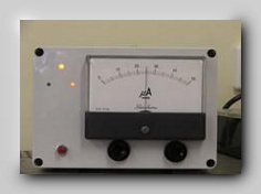
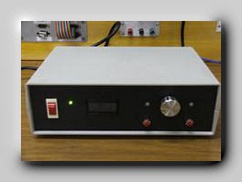
The rotator housing is an old heavy duty camera pan and tilt housing with the insides modified to “hopefully” turn the loop? I designed this unit to tilt over as it allows the loop to lay over and rest on a bracket on the roof. Shown below are the Loop tuning controller and Rotator control unit. I still have to do the front panels and the meter markings for the direction indicator which is currently showing N-S, the 3 LED’s show power, rotator shaft lock pin fully in and shaft lock pin fully out.
I incorporated a 1.8 deg stepper motor and a rotary encoder to turn and track the position of the 20 turn vacuum capacitor. This is connected to a control unit that I designed and wrote the Micro controller code for. It drives the stepper and displays the position on an LCD. Another rotary encoder is used to adjust the vacuum cap, also included are fast CW/CCW push buttons. Stop to stop (20 turns) in 7 seconds. One revolution of the encoder turns the cap about 1/10 of a turn. It is a dream to tune, however with a bigger vacuum capacitor I will have to use a 6 or 10 to 1 reduction drive between the stepper motor and the capacitor as the bigger unit will have more capacitive change per turn and you need around 0.02pf resolution to make tuning easy with the narrow bandwidth and high Q of the loop.
The Rotator has been finished. The brackets, bolts and paint are from my local hardware. The chain and cogs from the bike shop. The 60mm round pipe from the fence supply’s and the 75 and 100mm box section steel from the garage builders.
The rotator housing is an old heavy duty camera pan and tilt housing with the insides modified to “hopefully” turn the loop? I designed this unit to tilt over as it allows the loop to lay over and rest on a bracket on the roof. Shown below are the Loop tuning controller and Rotator control unit. I still have to do the front panels and the meter markings for the direction indicator which is currently showing N-S, the 3 LED’s show power, rotator shaft lock pin fully in and shaft lock pin fully out.
LH Picture at top of page
The 3/4" copper is coated in a plastic protection finish that is made especially for copper. This is not the final finish.
The 32mm x 32mm hardwood has been treated with a marine 2Pac preserver and is also waiting for a final topcoat of UV protecting paint.
The guy ropes will NOT be used when the unit is mounted on the tilt/rotator mast section.
The aerial was placed here to try it and to see if I should continue with it. The answer is YES!
Top Right of page
The loop has been mounted on the rotator and placed on the roof of the shack. It has been painted with UV protecting paint and there was no change to the resonant frequency.
Bottom Pictures
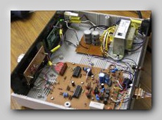
The Rotator controller and the Loop tuning controller. The tuning controller use’s 2 micro controllers. One controls the stepper motor via a rotary encoder that also includes fast clockwise and fast anticlockwise buttons.
The 2nd micro reads a rotary encoder attached to the shaft of the Vacuum cap and displays the cap position on an LCD display.
A lot of the components on the pcb are for standard RF suppression. Circuit and Micro code for downloading to come.
The 3/4" copper is coated in a plastic protection finish that is made especially for copper. This is not the final finish.
The 32mm x 32mm hardwood has been treated with a marine 2Pac preserver and is also waiting for a final topcoat of UV protecting paint.
The guy ropes will NOT be used when the unit is mounted on the tilt/rotator mast section.
The aerial was placed here to try it and to see if I should continue with it. The answer is YES!
Top Right of page
The loop has been mounted on the rotator and placed on the roof of the shack. It has been painted with UV protecting paint and there was no change to the resonant frequency.
Bottom Pictures
The Rotator controller and the Loop tuning controller. The tuning controller use’s 2 micro controllers. One controls the stepper motor via a rotary encoder that also includes fast clockwise and fast anticlockwise buttons.
The 2nd micro reads a rotary encoder attached to the shaft of the Vacuum cap and displays the cap position on an LCD display.
A lot of the components on the pcb are for standard RF suppression. Circuit and Micro code for downloading to come.
Moving from a large semi rural block to a small residential block has its drawbacks, more so if you love "Top band". A few years after the move I
decided to get back into amateur radio. I tried verticals of all kinds; base loaded, top loaded, centre loaded, helical wound, top hats, inverted-L
and even a dipole of sorts. I managed to get three 33m radials down and I tied my 6m x 9m shed and my 6m x 6m carport into the earth system,
but every time the results on 80m and 160m were hopeless. Most stations could hear me, some just! But receiving was an even bigger problem.
The noise in suburbia meant that I could hardly hear anything below S9. Most nights I had +20dB noise
with carriers and interference on the net frequencies. I almost gave it away as a bad joke - a 30 foot
height limit on any aerial by the local council didn't help. I then tried a small electrostatically shielded
receiving loop on 80m and the results were amazing! I could null the interference; stations buried in the noise were now readable, however a lot of the net participants had trouble hearing me on my vertical or inverted-L, I was one of the weaker signals.
I decided to try a magnetic loop antenna to see if it could work as well as the ARRL ANTENNA HANDBOOK data from Ted Hart suggested. The trouble is most of the web sites I visited were building small loops, running them on the desk inside the shack and then telling us how far down the loop is in performance when compared to the dipole at 40ft in their back yard. Huh! You think? Why not put the mobile car aerial on the desk and write a report about how far down in performance a vertical antenna is compared to a dipole at 40ft in the - well, you know the rest. Why not compare the loop indoors to a vertical or dipole mounted indoors - The results would at least have some meaning! Instead of typecasting the loop.
Click Image to
enlarge